Building #
Required Tools #
- 2mm hex key or screwdriver
- Soldering iron
Instructions #
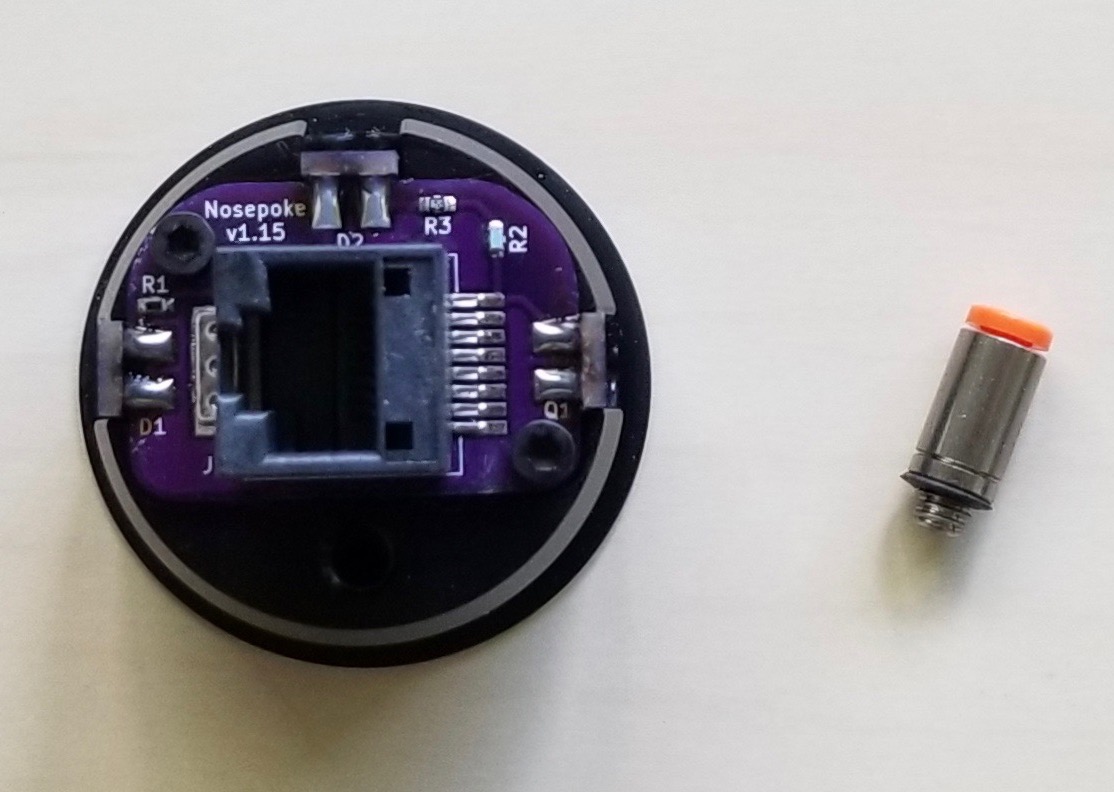
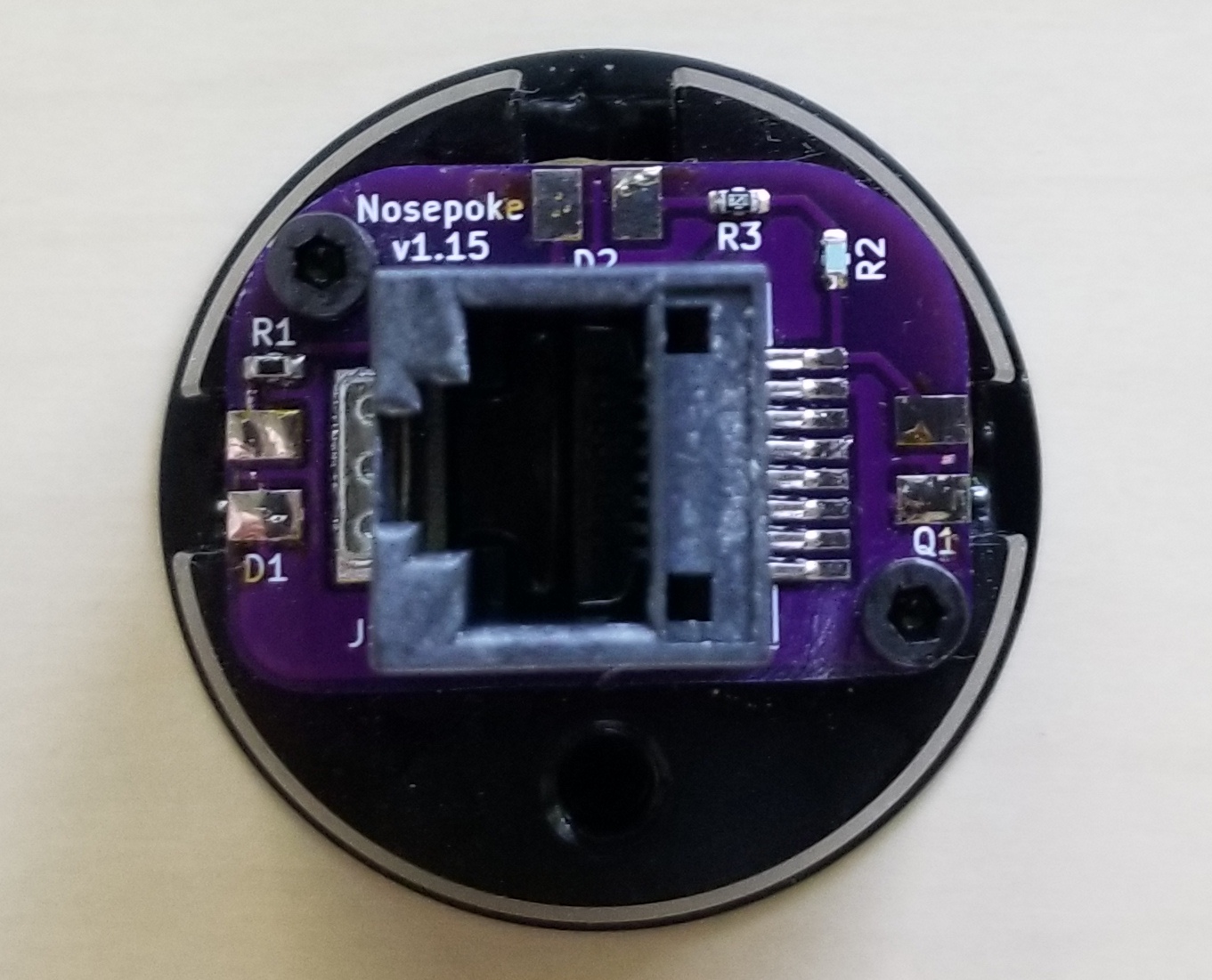
- Secure backside PCB to the back of the nosepoke using two M2.5 screws.
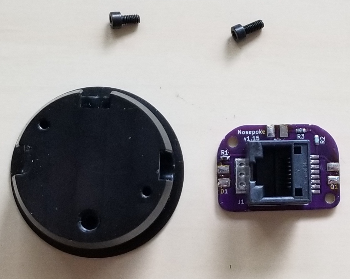
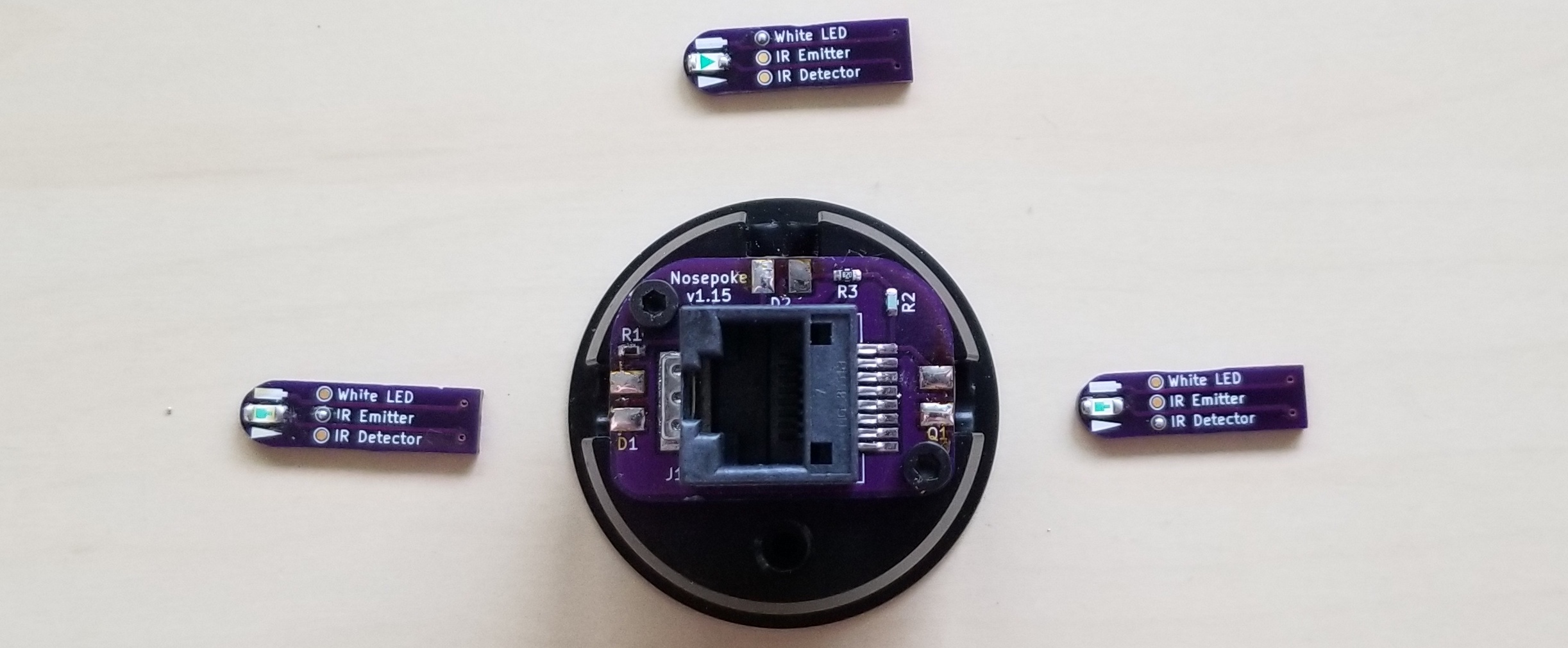
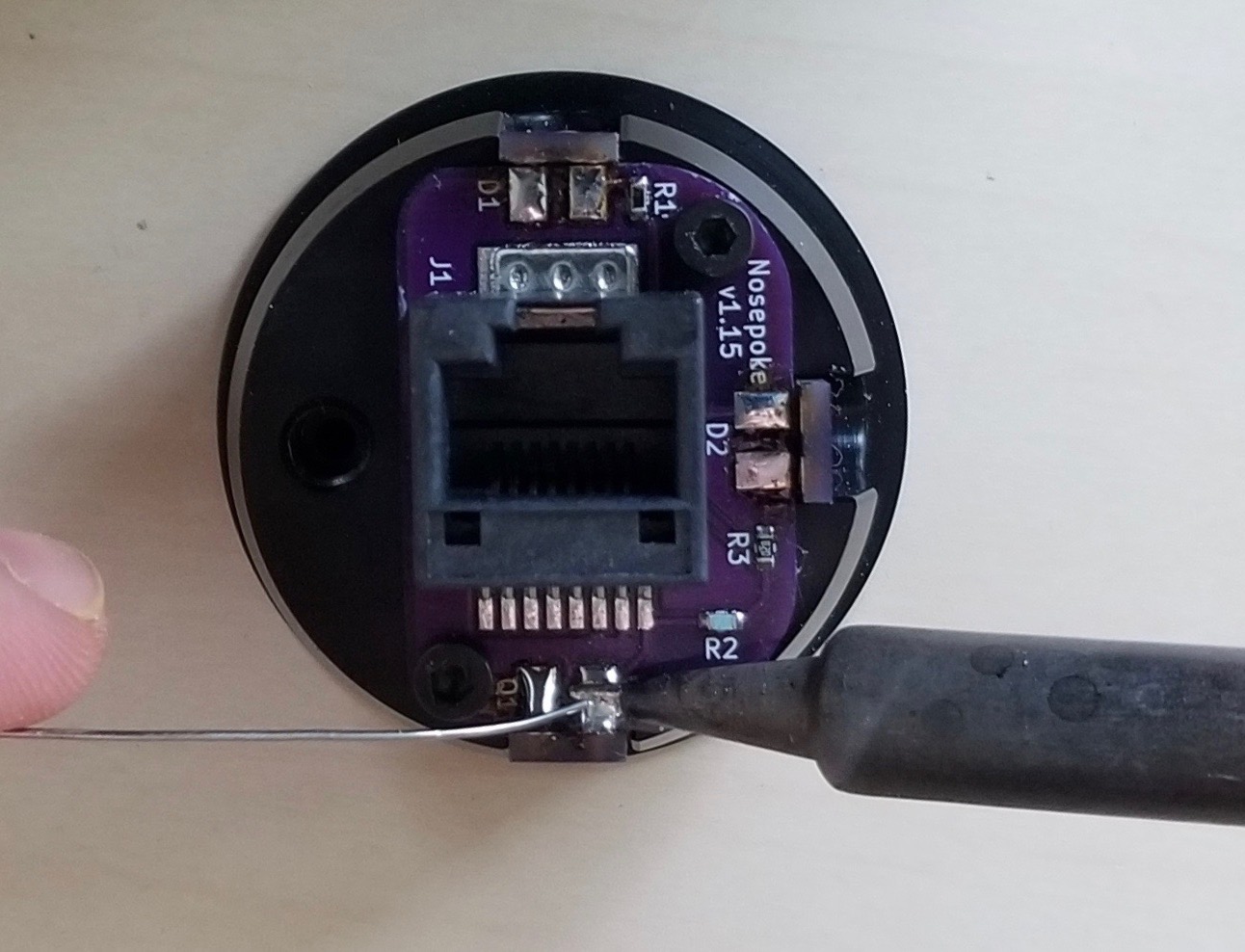
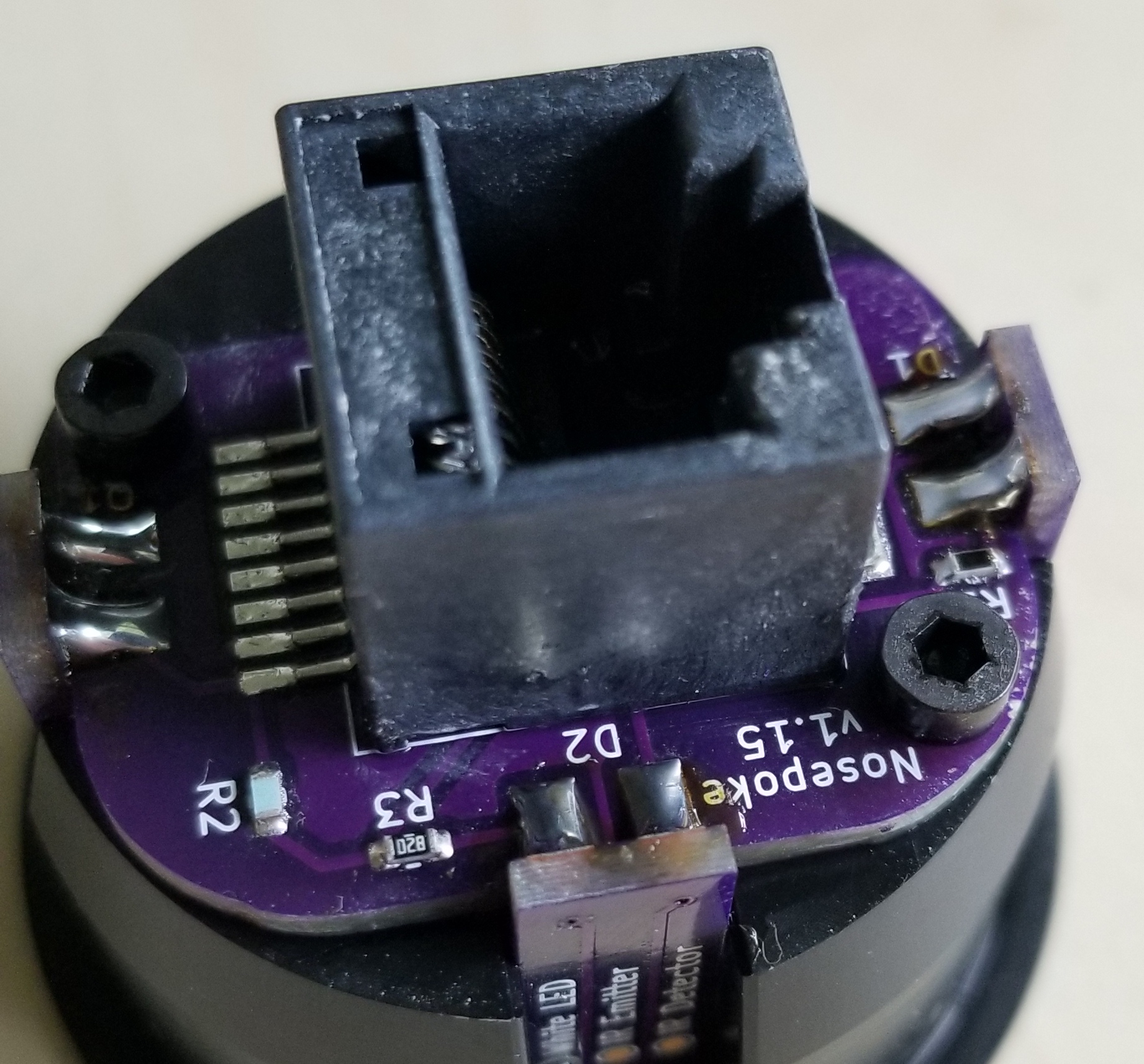
- Place the perimeter PCBs into the channels of the nosepoke and solder the joints of the PCBs to create both electrical and mechanical connections.
Note #
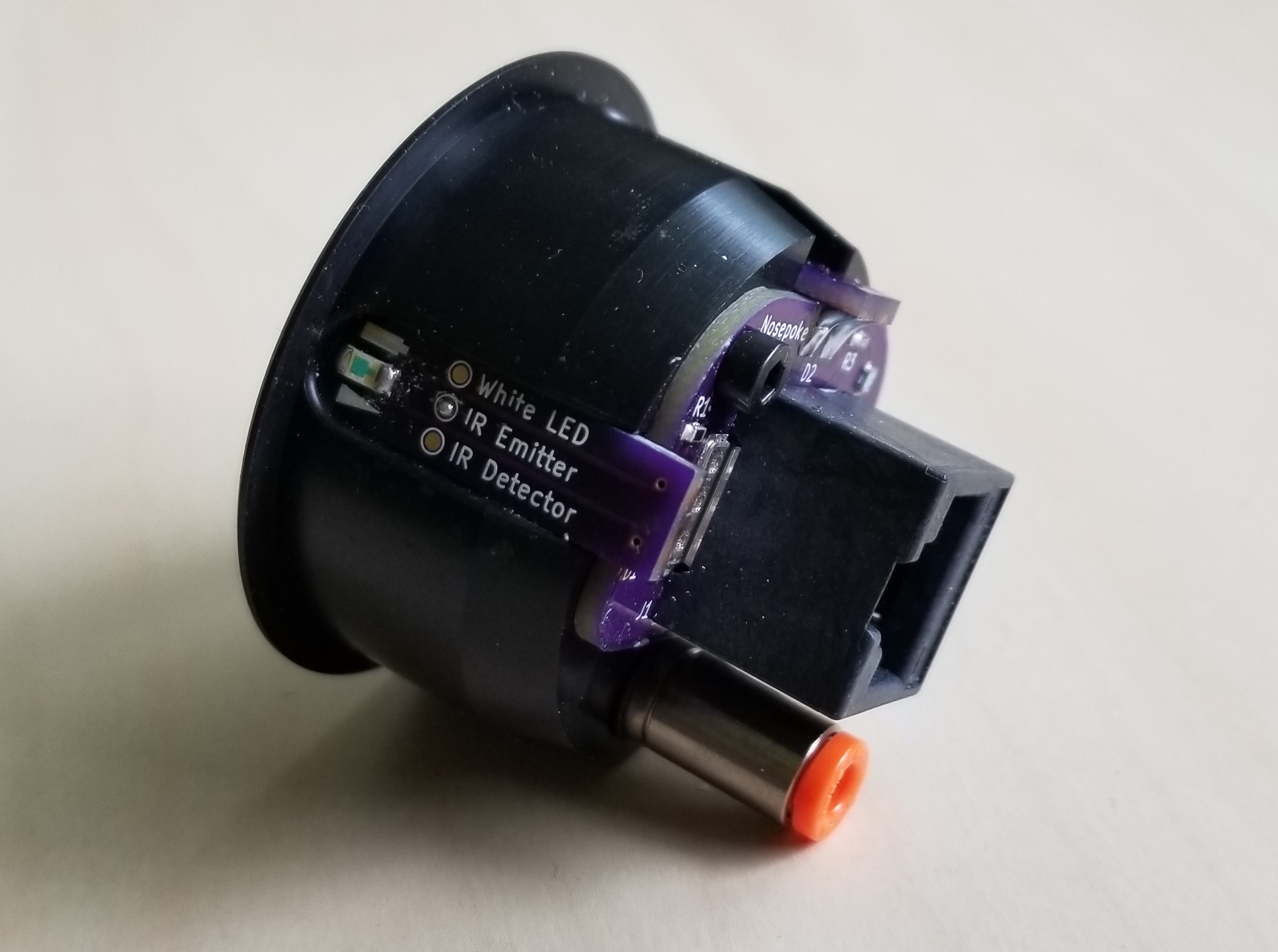
The IR emitter (D1) goes on the left side, the white LED (D2) goes on top and the phototransistor (Q1) goes on the right side.
- Using a 2mm hex key or screwdriver, screw in the push-to-connect fitting.