Head Implant
Required Tools
Ruler
Soldering iron
Tweezers
Bill of Materials
Qty |
Description |
Datasheet |
Order Link |
|---|---|---|---|
1 |
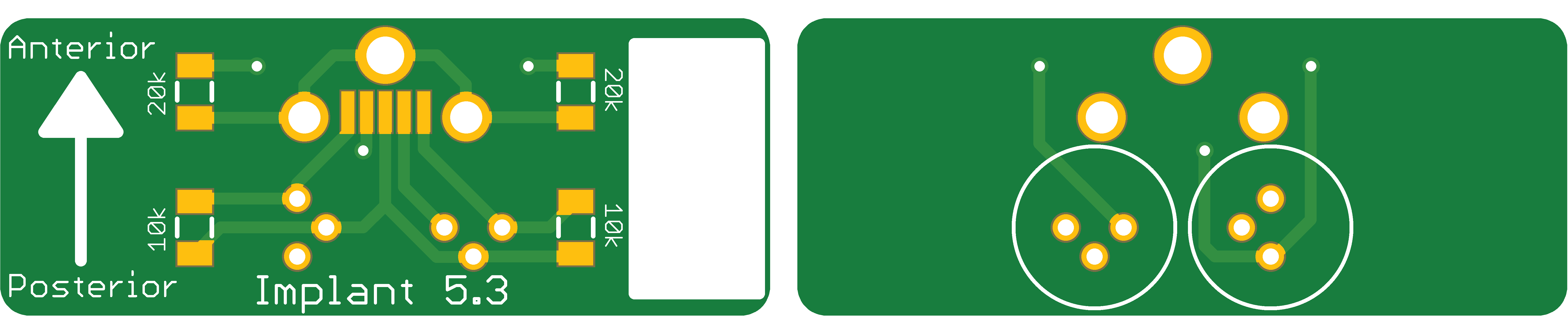
Implant PCB |
||
1 |
Laser Diode |
||
1 |
Fiber |
F-MBB |
|
1 |
UV curing adhesive |
||
1 |
Ferrule |
||
1 |
Epoxy |
||
2 |
Micro USB vertical socket |
||
2 |
Heat shrink tubing |
||
2 |
0603 10 kΩ Resistor |
||
1 |
0603 20 kΩ Resistor |
Assembly Instructions
Prepare Fiber
Tape down the fiber
Use a fiber stripper to remove the outer blue jacket from the fiber

Using a fiber cleaver, cut off the end of fiber to make a clean tip
Continue cutting the fiber into ~16mm pieces
Align Fiber
Insert laser diode into connector
Place connector in alignment jig
Place fiber in alignment jig
Turn on the power meter and connect to computer over usb
Open up the Thorlabs’ Power Meter Software
Establish the USB connection with Power meter by selecting the device and clicking “OK”

Adjust the following settings:
Range: 12mW
Wave: 520nm
Log Configuration
No of Samples: 20,000
Interval Time: 0.1
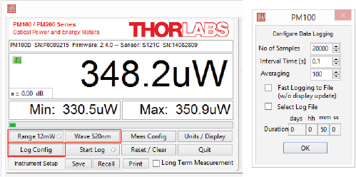
Click
Start Log
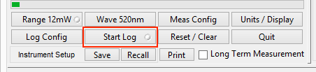
Set the power supply to 8.0 volts with a current limit of 300 mA
Provide power to the laser diode by pressing the “on/off” button
While watching the power graph update, use the 3-axis fiber launch system to adjust the x, y, and z alignment of the fiber with respect to the laser diode.
When you are happy with the alignment, apply UV curing adhesive to the fiber/laserdiode junction.
Cure the adhesive using UV light
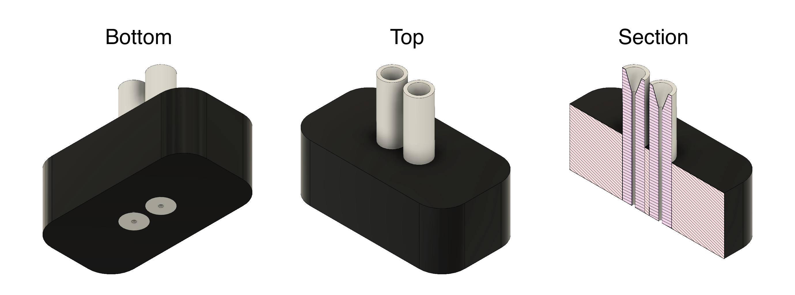
Fiber Guide Construction
A fiber guide is needed to ensure that the fibers are at a precise distance apart, and are parallel. The distance will depend on what area of the brain is being targeted. Below are files for 1.5 mm and 2.74 mm gap between fibers.
The laser cutter speed and power settings may need to be tweaked to get a good fit for the the ceramic ferrules.
Insert the ceramic ferrules into the acrylic fiber guide. The flat side of the ferrules should be flush with the face of the acrylic.
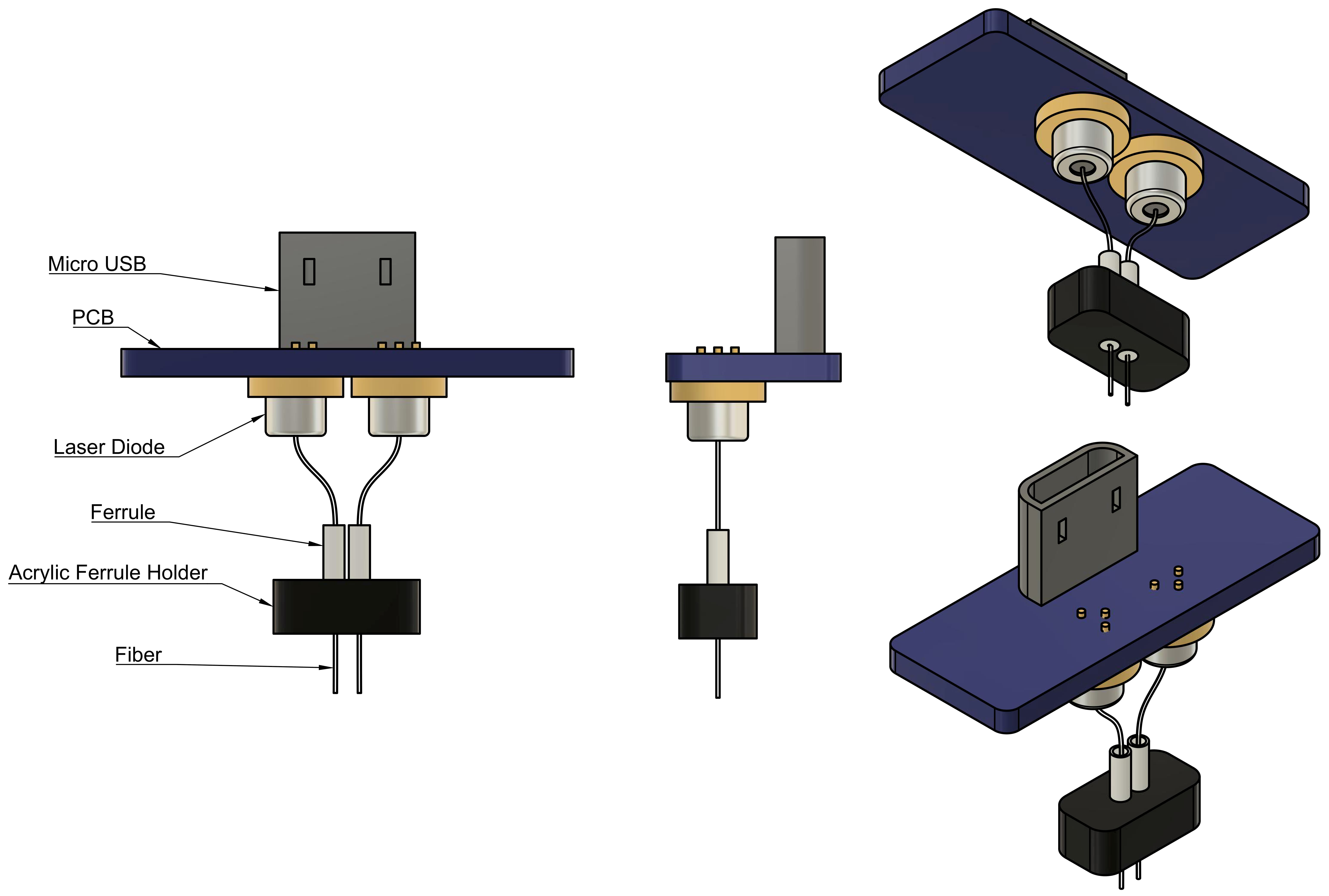
Combine PCB, Laser Diodes, and Fiber Guide
Solder the vertical microusb connector onto the PCB
Solder 1 leg of each laser diode onto the PCB
Bend the laser diodes toward eachother so the tips of the fiber slightly intersect near their tips
Solder the remaining legs of the laser diodes
Cut ~10mm of heat shrink tubing and slide it onto one of the laser diodes
Apply heat to the heat shrink tubing
Warning
Heat can weaken the UV glue that is used to attach the fiber. Be careful not to apply too much heat for too long as you may risk weakening the glue, causing the fiber to move out of alignment or detach completely.
Slide the fiber guide onto the two fibers. Adjust the
Surround the fibers and laser diodes with epoxy
Place heatshrink tubing around the clear epoxy section of the implant
Place and solder the remaining resistors onto the PCB